Start with the joint, not the bit
You tighten a screw, but the boards refuse to meet. Before you lean harder on the driver, look at what the screw is being asked to do: pass through one piece, grip another, and leave its head where you want it.
A pilot hole, a clearance hole, and a countersink solve different parts of that problem. Once you separate those jobs, you can plan a straightforward wood-to-wood connection without treating every small hole as the same thing.
This guide uses an ordinary, nonstructural scrap-wood practice joint to explain the geometry. It doesn’t supply a universal screw-size chart or replace the instructions for structural fasteners, wall anchors, cabinet hardware, or an engineered connection.
Know the three jobs
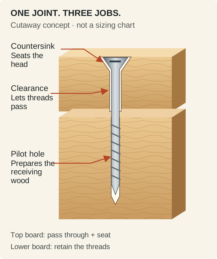
A pilot hole prepares the receiving wood for the screw’s threads. Think of it as a planned path through the piece that needs to hold the connection, rather than a hole that lets the entire threaded portion slide freely through.
A clearance hole has a different purpose: it allows the screw to pass through the first piece without the threads fastening that piece in place. That distinction matters when you want the screw head to draw the outer board toward the receiving board.
A countersink makes a tapered seat at the surface for a compatible countersunk head. It changes the mouth of the hole; it doesn’t substitute for the pilot or automatically create the clearance you need farther down.
Check the actual screw and hardware
Put the screw beside the parts before you select a bit. Identify the head shape, the threaded length, and any plain shank, then find the fastener maker’s recommendations for the material and intended connection.
Avoid choosing from the screw’s length alone. Two screws that look similar on the workbench can have different thread geometry, head requirements, or installation instructions, so a familiar-looking size isn’t enough information to commit to a hole.
If you’re attaching a hinge or bracket, inspect its existing holes as well. A tapered screw head belongs in a compatible seat; forcing a head into the wrong opening can leave poor contact even when the top appears tidy.
Draw the layers before you drill
Imagine adding a thin wooden face to a small, freestanding storage box. On paper, draw the face as the first layer and the box edge as the receiving layer, then mark where you want the head to finish.
Label the path through the face separately from the path into the box. This simple sketch tells you which material should let the screw pass and which material should retain the threads, without pretending the sketch specifies a safe load rating.
Now mark the back surface you must not break through. A screw or bit that reaches beyond it may damage something behind the work, so check the actual material thickness and the fastening instructions before selecting length or depth.
Prepare a stable practice setup
Use offcuts that match the material you intend to join, rather than sacrificing your finished piece to the first attempt. Mark the outer face, the receiving face, and a registration line so you can put the practice layers back in the same position.
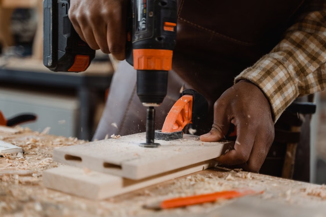
Support the assembly on a stable work surface and clamp small stock before drilling. CCOHS specifically advises against holding a small piece in one hand while operating the drill with the other, because the work can move or spin.
Follow your drill and bit instructions, use appropriate eye protection, and disconnect power before changing accessories. Keep the planned exit clear of the bench and clamps, and clear chips with a suitable brush after the tool has stopped.
Make the pilot and clearance deliberately
Choose the receiving hole from guidance for the exact screw and wood, then make a test on your offcuts. Don’t turn a rough visual comparison with the screw into a precise sizing rule, especially if the package provides an installation chart.
When the joint calls for clearance through the first board, keep that larger opening confined to the intended layer. If you enlarge the receiving hole along with it, the screw may no longer have the wood engagement you planned.
You can separate the pieces for that enlargement after preserving their alignment marks. This adds a setup step, but makes the distinction between the two holes easier to see and check during your first practice connection.
Cut a seat that matches the head
Use a countersink designed for the actual screw head, and begin conservatively on the scrap. Stop the tool and check the result with the screw; you can remove a little more wood, but you can’t put the original surface back.
The word countersink doesn’t establish the right geometry for every fastener. Lee Valley’s 82-degree tool is a specific documented design, so match the particular cutter to your screw instead of treating a familiar product name as a complete installation instruction.
A flat-bottomed counterbore is another shape again. Kreg’s Quick-Flip description specifically identifies that feature for its screw system, so don’t assume every product that drills a recess produces the tapered seat shown in this guide.
Understand combination bits and depth stops
A combination accessory can do more than one operation during the same setup, but read what each cutting section actually makes. Lee Valley’s 82-degree tool describes a clearance hole and a head seat; its name alone isn’t a promise of the receiving pilot you need.
Other adjustable countersink drills let you set pilot depth and the head recess separately. Those controls can save repeated adjustments, yet they still depend on the correct setup for your screw, material, and intended finished surface.
Treat a stop as a setting to verify on scrap, not a guarantee you can skip inspection. Confirm the cutter is secured as instructed and recheck after an adjustment, particularly before moving from a test joint to a visible project face.
Read the result before adding force
Bring the practice pieces together with their registration marks aligned, and drive the screw under control. Watch the gap and head position instead of judging success by how hard the handle becomes to turn.
If the boards remain apart, stop and inspect which layer is gripping the threads, whether debris is trapped between the faces, and whether the screw has reached its intended depth. Extra force doesn’t tell you which of those conditions is responsible.
If the screw spins without securing the assembly, stop before enlarging the damage. Reassess the receiving hole and the fastener’s suitability; don’t hide an uncertain connection under filler or treat a neat head as proof of holding strength.
Keep a useful test record
Write the screw’s exact product description on your offcut and note which bit you used for each operation. Add the wood type, the intended face, and any depth-stop setting that you verified, so your next attempt starts from something repeatable.
Keep the sample beside the finished work until you’ve checked the same head seating and board contact. If the real connection behaves differently, compare the materials and geometry first rather than assuming the practice result transfers automatically.
For a shelf support, overhead fitting, outdoor structural connection, or anything whose failure could injure someone, return to a documented fastening design. This little practice exercise teaches you to identify the holes; it doesn’t establish how much a real assembly can carry.
Before you drill the visible project parts, label your practice pieces as the upper board and receiving board, then write the intended screw, opening functions, and head position beside the sketch so you can compare the assembled result with the plan. If the boards don’t pull together or the head doesn’t sit as intended, stop and inspect which surface or opening is preventing that result instead of treating a tighter driver setting as the next automatic step.